1 November 2019
Edit on GitHub
— הפוסט זמין גם בעברית

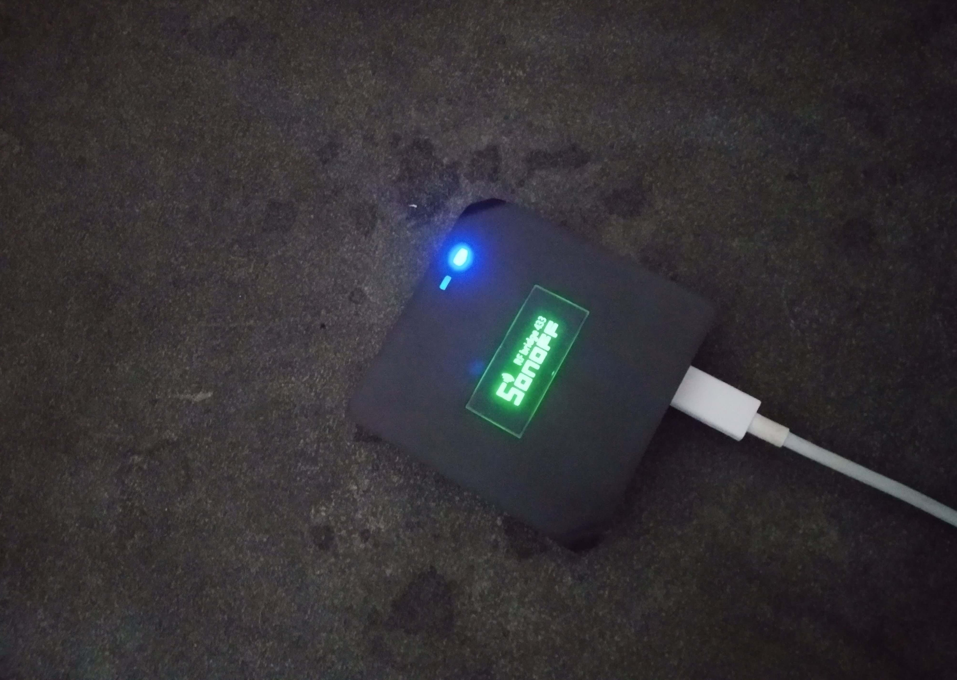
Flashing Tasmota on Sonoff RF bridge

Flashing Tasmota firmware on Sonoff RF Trasmitter/Recevier manual

Blog picture

Flashing manual for Sonoff RF bridge 433MHz.

Updated on 27/6/2020

Pictures of the device

Device
Device
Device
Device

Flashing equipment

These are the tools I used, you can buy from other sellers or similar tools.

Hardware equipment

  1. IR device (transmitter and receiver)
  2. Soldering iron and tin
  3. 2.54MM Pins
  4. Female Wires
  5. USB to TTL serial

Softwares to use

  1. PC with Windows 10 OS.
  2. download esptool flashing tool from here or directly from the official repo at GitHub.
  3. Tasmota firmware from here (version Tasmota v8.3.1 Fred) or directly from the official repo at GitHub.

Flashing the firmware

THE FLASHING PROCESS IS VERY DANGEROUS! BE AWARE, USING THE MANUAL IS AT YOUR OWN RISK!!!

Software settings

Create a folder and move to it the downloaded files tasmota.bin and e sptool.exe.

Let's assume the folder is C:\flasing

Connect the USB to Serial converter to the PC. Wait until the drivers are automatically installed by Windows. (if it doesn't work automatically, go here or here)

In Windows, search for device manager and select the first result, or press Windows Key + R and insert devmgmt.msc.

In the device manager, look for the device serial port COMX.

We will need it in the next step. In my case, it was COM6.

Device manager

Open the command line in the directory C:\flasing.

(If you don't know how, look here)

In the command line write the following command:

  esptool.exe -vv -cb 115200 -cp COM6 -ca 0x00000 -bz 1M -bm dout -cf tasmota.bin

Note that the COM6 should be replaced by your device port from earlier.

Do not press 'Enter' yet, keep the command ready-for-use for the next step

Disconnect the USB to Serial converter from the PC.

Now move to the next step:

Hardware settings

Opening the device

First of all, unplug the device from the power source, and do not connect it until flashing process is done

The device consists of two parts, which are connected with 4 screws.

Device screws

After you have opened the device, the board should look like this:

Device opend

Now, gently and carefully remove the board from the top of the plastic. The board should look like this:

Device board

Gently lift the thick black part with the white sticker at 90-degrees. (Be careful to not sever it from the board).

Make sure that it looks like this:

Device board ready

Now turn the switch in the panel to OFF mode.

Attached chart:

Device board ready

Soldering

We need to connect the device (while not connected to power!!!) to the PC via the converter.

The connection diagram is:

  • port 3v3 of the device to the 3v3 of the converter
  • port TXD of the device to the RXD of the converter
  • port RXD of the device to the TXD of the converter
  • port GND of the device to the GND of the converter

Photographs and diagrams of the connections:

Full wiring
Full wiring
Full wiring
Full wiring

Connecting to the PC

Make sure again that all wires are well connected.

Again, make sure all wires are wired correctly, everything is connected, and the on-board switch is OFF.

Now everything is ready for the ironing

Press on the Pairing Button.

Picture of the button's position:

Full wiring

Connect the converter to your computer while pressing and holding the button and in the command line window that you prepared earlier, press 'Enter'.

Assuming everything went well and we got the message flush complete,

Like this:

Full wiring

The flashing is finished!

Disconnect the converter from the computer, remove the soldered wires and return the switch on the board to ON mode. Gently reconnect the parts of the device and close it with the screws.

Setting the device

Make sure that all wires are removed, and the cover is in its place, then connect the device to the power source.

Make sure that you have disconnected all the wires and replaced the switch on the board to ON. Connect the device to a power supply.

Wait a few seconds and then a new network named sonoff-xxxx (tasmota-xxxx in the new versions) should appear in the WiFi list on a PC or smartphone.

networks

Connect to the new network.

Open the browser and open 192.168.4.1.

Enter your home SSID and the password (Tasmota supports two networks)

And then press 'Save'

ssid config

The device should reboot and connect to your home network.

Connect back to the home network, enter to the home router to get the new device IP address.

Each router has a different UI but all should have somewhere a table of network devices IPs.

In my router (ASUS RT-xxxxxx) it looks like this:

DHCP IPs

After you know the new device's IP (in my case, 192.168.1.36) open the browser and press the IP in the URL bar.

Then in the Web interface press Configuration and then Configure Other.

Replace the 'Template' content with:

{"NAME":"Sonoff Bridge","GPIO":[17,148,255,149,255,255,0,0,255,56,255,0,0],"FLAG":0,"BASE":25}

(From the template project, RF Bridge page)

and check the 'Activate' checkbox and press 'Save'.

The device should reboot again.

And that is it. you've finished.

Now you can use the device.

I recommend to see the Tasmota RF documentation here.

And again, Have fun!